
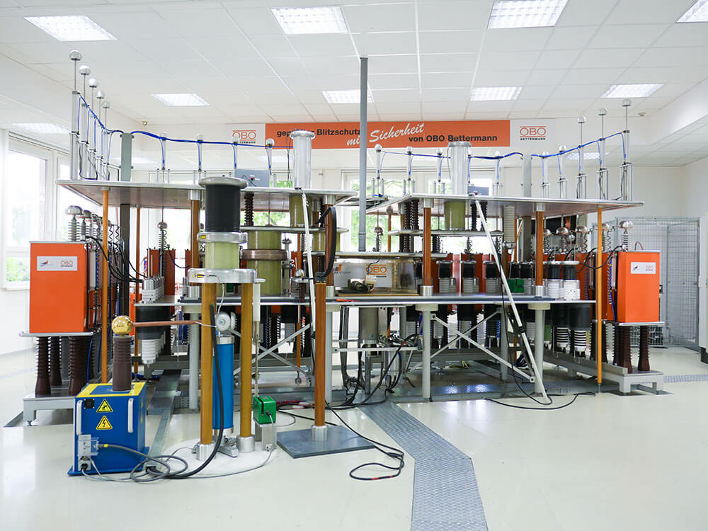
BET Testcenter: Tested Quality
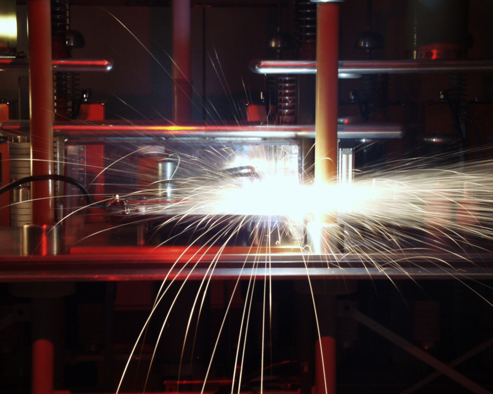
OBO products stand for the highest quality. To guarantee this, we do not only rely on external tests but also on our in-house BET Testcenter. Here, the quality, resilience and load-bearing capacity of OBO products are put to the test in extensive inspections and tests. Among other things, our highly qualified specialists test lightning protection components, lightning protection structures and surge protective devices. The effects of lightning events are also examined here from a scientific point of view.
Another focus of testing is the load-bearing capacity and resilience of cable support systems. The ultra-modern test facilities at the OBO Testcenter enable load simulations weighing several tons. The OBO test engineers test here not only during development, but also as part of certifications, according to specific requirements or at special customer requests.
The load capacity of underfloor systems is also put to the test in the BET Testcenter.
Quickstart


The following tests can be performed by OBO in the BET Testcenter:
- Cable Tray Systems: Testing according to DIN / EN / IEC 61537
- Electromagnetic Characteristics of Cable Management Systems: Testing according to DIN / CLC/TS 50659
- Underfloor Systems: Testing according to DIN / EN 50085-2-2
- Lightning Protection Components: Testing according to DIN / EN / IEC 62561
- Surge Protective Devices: Testing according to DIN / EN / IEC 61643
Electrically conductive, metallic cable management systems that are integrated into the equipotential bonding system shield the cables and lines laid in them against electromagnetic interference fields. The efficiency of shielding against magnetic fields is defined by the shielding effect of cable management systems and measured in accordance with clause 4 of DIN / CLC/TS 50659. For this purpose, the interference current induced in a conductor loop by the magnetic field of an impulse current is measured in a defined arrangement. The magnetic shielding effect of a cable management system is then 20 times the value of the logarithm of the ratio of the interference current in the conductor loop without cable management system to the interference current when the conductor loop is in the cable management system.
The transfer impedance is a further characteristic of electrically conductive metal cable management systems that is significant for evaluating electromagnetic interference. It results from the ratio of the voltage drop along a defined arrangement and an interference current flowing through this arrangement. The resulting voltage drop is a combination of the voltage drop that drops along the arrangement due to the interference current in the cable management system and the voltage drop that is induced by this interference current in a cable that is laid in the cable management system.
The transfer impedance measurement is carried out in accordance with clause 5 of DIN / CLC/TS 50659.
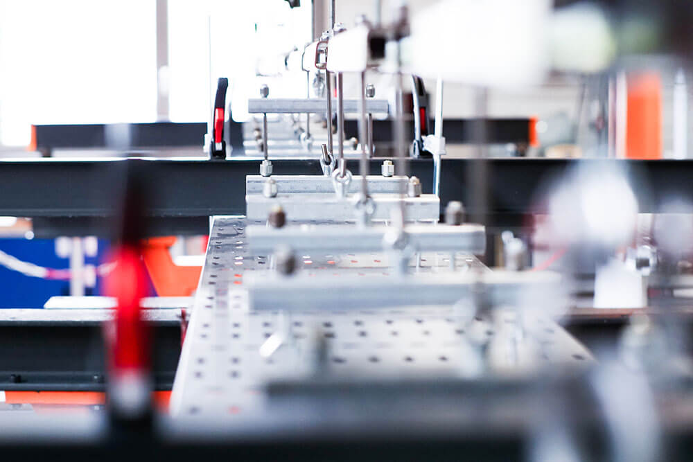
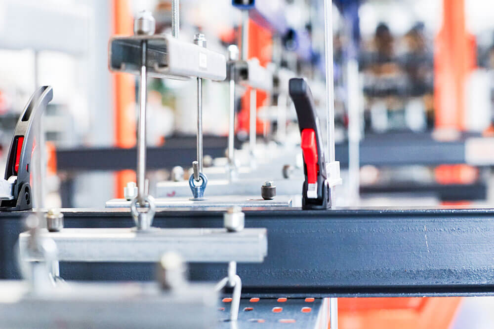
To ensure the load-bearing capacity of cable support systems, DIN / EN / IEC 61537 specifies tests for the safe working load (SWL) and defines the conditions of these tests. OBO has its own CTS test facility in the BET Testcenter to perform these tests. The CTS test facility is an in-house design from OBO Bettermann that has been continuously expanded and adapted to new requirements and conditions over the years.
Cable tray systems are installed in accordance with DIN / EN / IEC 61537. Depending on the length of the test arrangement, the test specimens are subjected to the load to be supported by means of two hydraulic cylinders with a total tensile force of 7 t. The resulting deformations are recorded by transducers and documented together with the existing force in kN/m. If the cable tray system has withstood the load successfully, it is increased by a factor of 1,7 to protect against failure. The deformation in relation to the load continues to be recorded.
With the CTS test facility, tests with loads from 0,05 kN/m to 4,9 kN/m are possible. The following tests can be performed in accordance with DIN / EN / IEC 61537:
Horizontal and vertical plane, horizontal direction of movement according to clause 10.3, 10.4 and 10.5 with support distances
- up to 7 m as a multi-span structure
- up to 15 m as a single-span structure
Cable tray or cable ladder systems as well as individual elements supporting such systems (i.e. cantilever brackets and pendants) are subjected to save working load in accordance with DIN / EN / IEC 61537. During the test, the CTS test facility records the actual force and the corresponding deformation. The test facility is capable of 25 kN tensile force.
The mechanical strength of cable tray systems and cable ladder systems is tested by an impact test with the pendulum hammer. The pendulum hammer tester in the BET Testcenter can test up to 50 J. According to DIN / EN / IEC 61537, this test is not required for metallic systems.
A further test, that can be performed with the CTS facility in the BET Testcenter, is the test of electrical continuity of cable tray and cable ladder systems according to clause 11 of DIN / EN / IEC 61537. It ensures the equipotential bonding and the connection to earth.
System components that are not subject to a corrosion class in test standard DIN / EN / IEC 61537 can be tested in a salt spray test in the salt spray chamber. The neutral salt spray test (NSS) according to ISO 9227 enables the corrosion resistance of unclassified corrosion protection to be assessed. This test is also often used to compare similar kinds of corrosion protection.
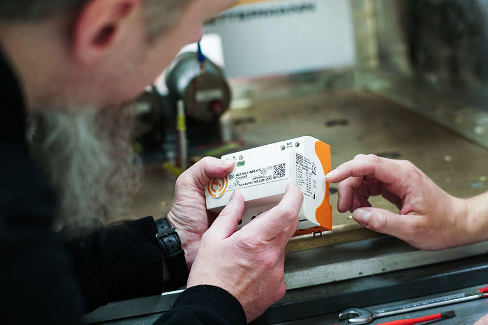
The standard series DIN / EN / IEC 61643 demands several performance and safety tests to prove the discharge capability and correct performance of surge protective devices (SPDs). These tests also ensure the safety of SPDs in case of system failures.
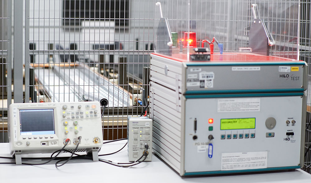
With the lightning current generator in the BET Testcenter the performance and discharge capability of type 1 and type 2 SPDs can be tested. It provides 8/20 and 10/350 current impulses up to 200 kA. The lightning current generator contains an ohmic capacitive differential voltage divider system, that measures up to 10 kV.
In addition, for the operating duty test, an AC power source is available, which is connected parallel to the lightning current generator and is capable to deliver prospective short circuit currents up to 3,5 kA at 190 V and 255 V and 1,5 kA at 440 V.
Our combination wave generators are capable of delivering up to 24 kV (1,2/50) / 12 kA (8/20). With the addition of a 498 Ω resistance, front of wave sparkover measurements for switching and combined SPDs according to CTL decision sheet DSH 2006 are possible.
Total discharge current measurements can be performed with SPDs up to 4 live conductor connections. The current through each live conductor can be measured up to 60 kA for 8/20 and 10/350 current impulses.
Limiting voltage and leakage currents can also be tested in the BET Testcenter.
The DIN / EN / IEC 62561 standard series demands several tests such as lightning impulse currents, electrical, mechanical and environmental tests. This is how an adequate lightning current impulse and capability and a resistance against environmental stresses can be proven.
The following tests can be performed with the facilities of the BET Testcenter:
The conditioning tests (aging tests) required in the DIN / EN / IEC 62561 series can be carried out in a salt spray chamber and a Kesternich facility. The cyclic salt spray test (test method 2) described in IEC 60068-2-52 can be carried out. The treatment in a humid sulphurous atmosphere according to ISO 6988 is carried out in the Kesternich facility.
Lightning current tests from the DIN / EN / IEC 62561 series with up to 200 kA with a wave shape of 10/350 and 8/20 can be carried out with the lightning current generator. Lightning protection system components such as connection components, conductor materials, isolating spark gaps, lightning counters and components for isolated lightning protection systems can be tested.
Further electrical tests, such as testing the contact resistance or the resistivity of conductor materials, as well as insulation resistance measurements, are possible using various measuring methods.
With the combination wave generator, impulse sparkover voltages of up to 24 kV (1,2/50) and current impulses up to 12 kA (8/20) can be tested.
With the high-voltage test devices, voltage rises of 100 V/s up to 5 kV AC and up to 6 kV DC can be tested.
In addition, several mechanical test, like impact test with the pendulum hammer, can be performed.
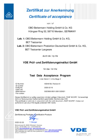
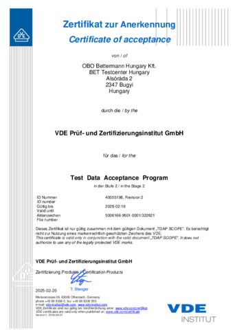
Certificates
Decision rule describing how measurement uncertainty is taken into account in statements of conformity to a particular requirement: Conformity statements are decided according to IEC Guide 115, unless otherwise specified in the applied test standard.